Whats a Servo?
A Servo is a small device that has an output shaft. This shaft can be positioned to specific angular positions by sending the servo a coded signal. As long as the coded signal exists on the input line, the servo will maintain the angular position of the shaft. As the coded signal changes, the angular position of the shaft changes. In practice, servos are used in radio controlled airplanes to position control surfaces like the elevators and rudders. They are also used in radio controlled cars, puppets, and of course, robots.

A Futaba S-148 Servo
Servos are extremely useful in robotics. The motors are small, as you can see by the picture above, have built in control circuitry, and are extremely powerful for thier size. A standard servo such as the Futaba S-148 has 42 oz/inches of torque, which is pretty strong for its size. It also draws power proportional to the mechanical load. A lightly loaded servo, therefore, doesn't consume much energy. The guts of a servo motor are shown in the picture below. You can see the control circuitry, the motor, a set of gears, and the case. You can also see the 3 wires that connect to the outside world. One is for power (+5volts), ground, and the white wire is the control wire.

A servo disassembled.
So, how does a servo work? The servo motor has some control circuits and a potentiometer (a variable resistor, aka pot) that is connected to the output shaft. In the picture above, the pot can be seen on the right side of the circuit board. This pot allows the control circuitry to monitor the current angle of the servo motor. If the shaft is at the correct angle, then the motor shuts off. If the circuit finds that the angle is not correct, it will turn the motor the correct direction until the angle is correct. The output shaft of the servo is capable of travelling somewhere around 180 degrees. Usually, its somewhere in the 210 degree range, but it varies by manufacturer. A normal servo is used to control an angular motion of between 0 and 180 degrees. A normal servo is mechanically not capable of turning any farther due to a mechanical stop built on to the main output gear.
The amount of power applied to the motor is proportional to the distance it needs to travel. So, if the shaft needs to turn a large distance, the motor will run at full speed. If it needs to turn only a small amount, the motor will run at a slower speed. This is called proportional control.
How do you communicate the angle at which the servo should turn? The control wire is used to communicate the angle. The angle is determined by the duration of a pulse that is applied to the control wire. This is called Pulse Coded Modulation. The servo expects to see a pulse every 20 milliseconds (.02 seconds). The length of the pulse will determine how far the motor turns. A 1.5 millisecond pulse, for example, will make the motor turn to the 90 degree position (often called the neutral position). If the pulse is shorter than 1.5 ms, then the motor will turn the shaft to closer to 0 degress. If the pulse is longer than 1.5ms, the shaft turns closer to 180 degress.

As you can see in the picture, the duration of the pulse dictates the angle of the output shaft (shown as the green circle with the arrow). Note that the times here are illustrative, and the actual timings depend on the motor manufacturer. The principle, however, is the same.
Servomechanism

1. electric motor
2. position feedback potentiometer
3. reduction gear
4. actuator arm
A servomechanism, or servo is an automatic device which uses error-sensing feedback to correct the performance of a mechanism. The term correctly applies only to systems where the feedback or error-correction signals help control mechanical position or other parameters. For example an automotive power window control is not a servomechanism, as there is no automatic feedback which controls position -- the operator does this by observation. By contrast the car's cruise control uses closed loop feedback, which classifies it as a servomechanism.
Servomechanisms may or may not use a servomotor. For example a household furnace controlled by thermostat is a servomechanism, yet there is no closed-loop control of a servomotor.
A common type of servo provides position control. Servos are commonly electrical or partially electronic in nature, using an electric motor as the primary means of creating mechanical force. Other types of servos use hydraulics, pneumatics, or magnetic principles. Usually, servos operate on the principle of negative feedback, where the control input is compared to the actual position of the mechanical system as measured by some sort of transducer at the output. Any difference between the actual and wanted values (an "error signal") is amplified and used to drive the system in the direction necessary to reduce or eliminate the error. An entire science known as control theory has been developed on this type of system.
Servomechanisms were first used in military fire-control and marine navigation equipment. Today servomechanisms are used in automatic machine tools, satellite-tracking antennas, automatic navigation systems on boats and planes, and antiaircraft-gun control systems. Other examples are fly-by-wire systems in aircraft which use servos to actuate the aircraft's control surfaces, and radio-controlled models which use RC servos for the same purpose. Many autofocus cameras also use a servomechanism to accurately move the lens, and thus adjust the focus.
Typical servos give a rotary (angular) output. Linear types are common as well, using a screw thread or a linear motor to give linear motion.
Another device commonly referred to as a servo is used in automobiles to amplify the steering or braking force applied by the driver. In this form this device is not a true servo, but rather a mechanical amplifier.
In industrial machines, servos are used to perform complex motion.
RC servos
RC servos are servos typically employed in industrial robotics, automation, and radio-controlled models. They are also used to provide actuation for various mechanical systems such as the steering of a car, the flaps on a plane, or the rudder of a boat.
RC servos are comprised of a DC motor mechanically linked to a potentiometer. Pulse-width modulation (PWM) signals sent to the servo are translated into position commands by electronics inside the servo. When the servo is commanded to rotate, the DC motor is powered until the potentiometer reaches the value corresponding to the commanded position that it's ordered.
Due to their affordability, reliability, and simplicity of control by modern microprocessors, servo motors are often used in small-scale robotics applications.
The servo is controlled by three wires: ground (black/orange), power (red) and control (brown/other colour) and will move based on the pulses sent over the control wire. This wiring sequence is not true for all servos, for example the S03NXF Std. Servo is wired as brown(negative), red (positive) and orange (signal). The pulses sent over the control wire set the angle of the servo horn. The servo expects a pulse every 20 ms in order to gain correct information about the angle. The width of the servo pulse dictates the range of the servo's angular motion.
A servo pulse of 1.5 ms width will set the servo to its "neutral" position, or 90°. For example a servo pulse of 1.25 ms could set the servo to 0° and a pulse of 1.75 ms could set the servo to 180°. The physical limits and timings of the servo hardware varies between brands and models, but a general servo's angular motion will travel somewhere in the range of 180° - 210° and the neutral position is almost always at 1.5ms.
Servo motors are often powered from nickel-cadmium battery packs common to most RC devices. Voltage ratings vary from product to product, but most servos are operated at 4.8 V DC or 6.0 V DC (a 4 or 5 cell battery).
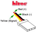
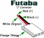
Servo WiringAll servos have three wires:
Black or Brown is for ground.
Red is for power (~4.8-6V).
Yellow, Orange, or White is the signal wire (3-5V).
Servo Voltage (Red and Black/Brown wires)
Servos can operate under a range of voltages. Typical operation is from 4.8V to 6V. There are a few micro sized servos that can operate at less, and now a few Hitec servos that operate at much more. The reason for this standard range is because most microcontrollers and RC receivers operate near this voltage. So what voltage should you operate at? Well, unless you have a battery voltage/current/power limitation, you should operate at 6V. This is simply because DC motors have higher torque at higher voltages.
3 comments:
Nice work dude!
Hi Ninni,
nice tutorial, should be helpful; for a lot of beginners into the world of robotics.
Btw, are you aware of any shops in Hyderabad that stock good servo or dc motors for electronics enthusiasts ?, if yes please let me know.
- Deepesh.
Hi Ninni,
good tutorial and very useful for beginners like me .
the same Question as deepesh's please let us know if you are aware of any shops in Hyderabad that stock good servo or dc motors .
-vijay
Post a Comment